DISCLAIMER
This case study is based on a conference paper presented at the 73rd International Astronautical Congress (Paris), intended to showcase some of the features and capabilities of IENAI SPACE’s cutting-edge space mobility software tool: 360™. This study shows the capabilities of 360™’s Concurrent Subsystem Design Module, highlighting the advantages of a concurrent design approach within the selection process of propulsion systems for small satellites. Additionally, 360™’s Propulsion System Design Module is presented as well, highlighting the benefits that a modular propulsion system, such as our ATHENA™ thruster, can bring to a space mission.
TL;DR
- The concurrent design of the propulsion system, maneuvers, and highly coupled subsystems allow for obtaining improved system-level optimal solutions if compared to subsystem-level optimization.
- 360™ by IENAI SPACE, our advanced space mobility analysis software tool, enables the exploration of spacecraft subsystems’ design options concurrently with the optimization of propulsive maneuvers and operations, producing realistic optimal solutions throughout the design lifecycle.
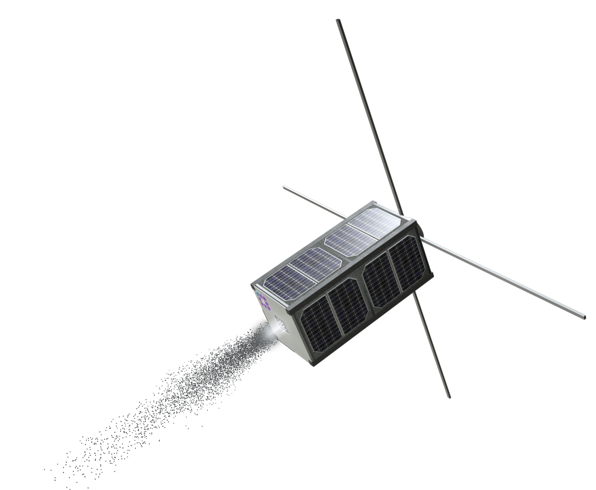
- ATHENA™, with its modular and customized approach, allows for minimizing the mass and cost of the propulsion system, avoiding carrying excess mass and reducing the footprint on the mission.
MOTIVATION
Have you ever started designing a constellation and reached the conclusion that there are too many products and options on the market? How do you choose what is best for your mission? IENAI’s answer is concurrent engineering, and we have the right tool for you!
Most of the current propulsion system solutions in the market follow a Commercial Off-The-Shelf (COTS) approach, aiming at reducing the integration and verification costs. While this approach is reasonable for components like attitude sensors, antennas or on-board computers, the propulsion system is inherently dependent on the mission to be performed, and a certain degree of variability should be allowed. Even more, the difficulty in finding the COTS propulsion system that closely matches the mission needs can lead integrators to build the satellite around the propulsion system.
To deal with this complex multi-disciplinary problem inherent to space mobility, at IENAI SPACE we have developed GO™ and 360™, a suite of software tools that can be used to computer-generate design solutions for ATHENA™. Good news, GO™, our intuitive thruster design tool is available in open access. Feel free to try it out! And as for 360™ by IENAI SPACE it will be available by early Q2 2023.
If you are interested in joining the closed beta, send an email to 360@ienai.space.
MISSION DESCRIPTION
This case study will focus on 360™, which as it will be clear in a minute, is a powerful instrument that can do much more within the space mobility problem. It proposes the example of a LEO constellation composed of 6U CubeSats whose properties are based on NanoAvionics 6U bus and the relevant parameters are reported in Table 1. Within this mission, the propulsion system fulfills the functions of deployment/roll-up of the constellation, maintenance, and space sustainability maneuvers.
To keep this case study concise, we focus on the maneuvers for the deployment/roll-up of the constellation (these maneuvers are fundamental for reducing the cost of constellation deployment, so check out our paper on constellation deployment!), although 360™ can perform analysis of full missions, considering all the maneuvers involved within its versatile and holistic approach, described in the previous section.
Tab. 1: Spacecraft properties and constellation geometry
| Property | Value | Unit |
|---|---|---|
| Spacecraft mass | 8.0 | kg |
| Surface area | 0.03 | m² |
| Form factor | 6 | U |
| Nominal altitude | 650.0 | km |
| Nominal eccentricity | 0.003 | - |
| Nominal inclination | 97.73 | ° |
| Plane spacing (ΔΩ) | 5 | ° |
In short, in this case, we need to define the orbit injection to optimize the deployment time/parameter. Other than the optimization of the maneuver, we are interested in designing a system that allows us to fulfill the mission while minimizing some metrics of interest. For example, usual optimization objectives can be the system’s mass, which relates to the launch cost, the cost of the system itself or its volume, and so on. But there can be other objectives, more related to the operations and time, such as the time to perform a given maneuver.
The typical output of these multi-objective problems is a so-called “Pareto front”, as shown in Fig. 1. The Pareto front is part of the feasible solutions, and it represents the optimal solutions with respect to the objectives considered.
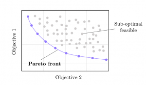
In this problem, we consider the payload fraction (namely, we want to minimize the mass of the subsystems that are not the payload) as an objective to maximize, and the deployment maneuver duration, which needs to be minimized. As it will be shown in the results, these two objectives are opposed, if we want to increase the payload fraction, we will have longer deployments and vice-versa.
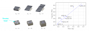
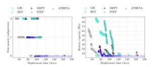
Finally, this problem considers the design/selection of the propulsion system and of the electrical power system. Mainly, for the Electrical Power System (EPS), three discrete configurations for the solar panels are considered (from body mounted to double-deployable panels), while iterating on the battery capacity, as shown in Figure 2. The propulsion system design variables for ATHENA™ (our customizable electrospray-based propulsion system, follows a modular and customized approach that allows it to be tailored to any platform and mission) are the number of thruster heads, namely the elementary unit producing thrust (which impacts the thrust level, power, and mass of the system), and the propellant mass carried on board (which affects the mass of the system and the total impulse deliverable).
Finally, to show the advantages of a tailored and custom propulsion system against the COTS approach, several representative technologies of electric propulsion COTS are presented in Tab. 2. Note that 360™ is a propulsion system-agnostic analysis tool, in fact, it allows for analyzing any kind of propulsion system, as long as a model is available. This way, 360™ can perform the optimization of the operational point for these systems as well.
Tab. 2: Propulsion system properties considered (*depends on configuration)
| System | Thrust (mN) | Specific impulse (s) | Wet mass (kg) | Propellant mass (kg) | Power (W) |
|---|---|---|---|---|---|
| FEEP | 0.05 - 0.42 | 2000 - 6000 | 0.9 | 0.22 | 20 - 40 |
| MEPT | 0.3 - 0.8 | 300 - 600 | 2.5 | 0.56 | 30 - 60 |
| GIE | 0.3 - 1.2 | 300 - 2600 | 1.84 | 0.84 | 34 - 66 |
| HET | 2.2 - 2.8 | 700 - 890 | 1.9 | 0.1 | 50 - 65 |
| ATHENA™ | 0.1 - 0.43 | 1600 - 2000 | * | * | < 12 |
RESULTS
Before diving into the results, an example of a complex constraint is presented, to highlight the high-fidelity simulation capabilities of 360™. In this case study, in fact, the battery state-of-charge (SOC) is simulated considering the input power (which depends on the orientation of the solar panels with respect to the Sun) and the dynamic power consumption of the subsystems modeled in the spacecraft.
In Figure 3 it is possible to see that when the thruster is on, producing thrust, the SOC decreases; when a given safety threshold is reached, the thruster is switched off, and the spacecraft goes into Sun-pointing mode to recharge the batteries.
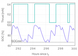
This kind of constraint limits the performance of the thruster, and a propulsion system with higher power consumption will cause the battery to drain faster, allowing only for shorter firing arcs and needing more frequent recharging periods. Eventually, even if a system has more thrust than another, but it requires more power, it might lead to longer maneuvers duration, due to the lower duty cycle. This aspect is related to the efficiency of the propulsion system, which plays another fundamental role in minimizing the propulsion system footprint, and in IENAI SPACE we are working hard to bring to the market ATHENA™ the highest-efficiency propulsion system in its category, by a factor 2!
ATHENA™ design example with 360™
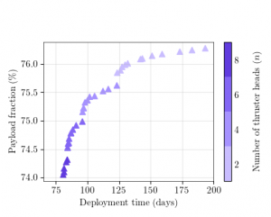
Going step-by-step, we start with the design of ATHENA™ for a given spacecraft configuration (fixed power system). Figure 4 shows the Pareto front for the two objectives and highlights the number of thruster heads needed: each triangle is an optimal solution with regard to the two objectives. This is a perfect example of the kind of actionable information that 360™ provides: the mission analyst has the freedom to select one or more of these solutions for more detailed analysis, being confident that already at early stages the solution is realistic (thanks to the high-fidelity modeling) and close to the optimum.
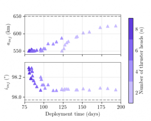
It is interesting to notice that the design of the thruster, in this case, is coupled and driven by the optimization of the maneuver itself. In fact, Figure 5 shows how the injection point (and consequently the maneuver to be performed) changes with the deployment time. Faster deployments can be obtained by performing larger maneuvers, hence needing heavier propulsion systems solutions (with more propellant and more thruster heads).
Comparison of propulsion systems
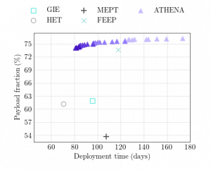
As a natural follow-up, it is interesting to compare how ATHENA™ performs compared to other COTS propulsion systems. In Figure 6 the solutions obtained with ATHENA™ are compared to the other systems defined in Table 2. ATHENA™ clearly provides more flexibility at the design stage, offering many different solutions (thanks to its modularity) versus the single solution of the fixed COTS (optimized in terms of the operational point) and additionally, its footprint in terms of mass is significantly lower for this class of satellites. The only system competing on this last point is the FEEP, which however, due to its very low thrust, limits the deployment time to about 120 days, while ATHENA™ can perform it about 30% faster for comparable system mass.
The HET solution is the only system that can perform faster maneuvers (about 10 days faster) than ATHENA™, however at the cost of 12% less payload fraction available. The wet mass of our system is 50% lower, thanks to the tailoring of the size of the tanks and the number of thruster heads used!
Concurrent subsystems design with 360™
Following up, we explore what happens if we allow 360™ to explore Electrical Power System (EPS) design solutions (battery capacity and solar panel configuration) concurrently with the maneuver and the propulsion system sizing.
The new Pareto front obtained (shown in Figure 7) represents a set of improved solutions compared to the previous case. The combined design unlocked faster solutions and a new Front that performs the maneuver for the same time but for a lower cost in terms of the mass of the whole system.
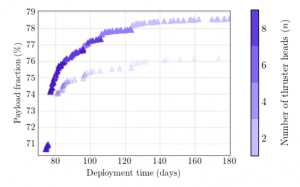
This means that the EPS for those solutions was too large and could have been made smaller, if only we used a more holistic approach in the design process, as we are doing now, thanks to 360™! Additionally, we notice how the number of heads spreads in a less uniform way as a function of the EPS design, highlighting the complexity of this design problem.
If we compare, once more, against COTS thrusters in Figure 8, we see that now also the COTS generate Pareto fronts (which are given by the variation of the EPS and the optimization of the power level of the thruster), and we see improvements compared to the previous case: most of the system find faster solutions.
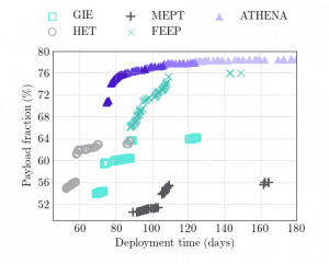
Figure 9 shows the solutions found for the EPS and for all the propulsion systems considered: faster deployment requires more thrust, hence bigger solar panels and battery capacities. As for the mass, it is interesting to notice that ATHENA™ requires smaller batteries on average, and this is related to the higher efficiency of the propulsion system, ultimately leading to cost savings as well!
360™ can deal with this kind of analysis, considering an arbitrary number of objectives and design variables, for example considering cost or volume as additional optimization objectives, and it can easily perform trades between all these variables and subsystems, depending on the mission needs.
CONCLUSIONS
This case study presented some of the features of our cutting-edge space mobility analysis tool 360™ by IENAI SPACE. We have shown how 360™ can solve multi-disciplinary, multiobjective space mobility-related optimization problems, with application to the concurrent design of space systems and in particular the propulsion system, the coupled subsystems, and associated orbital maneuvers.
Additionally, we applied 360™ capabilities for the design of our modular and customized ATHENA™ thruster, showing how a modular system offers far greater flexibility and exploration of candidate options if compared to non-modular, COTS propulsion systems.
We highlight that:
- A concurrent design approach for the propulsion system, the propulsive maneuvering phases, and the highly coupled subsystems, such as the power and attitude control systems, leads to improved system-level optimal solutions if compared to a subsystem-level optimization approach.
- 360™ by IENAI SPACE, our advanced space mobility analysis software tool, allows exploring spacecraft subsystems’ design options concurrently with the optimization of propulsive maneuvers and operations, producing realistic optimal solutions throughout the design lifecycle. The core architecture of 360™ is versatile and robust enough to handle multiple variables, multiple objectives, and operational constraints, generating sets of optimal solutions rapidly and effectively.
- Our modular and high-efficiency ATHENA™ propulsion system allows for minimizing the mass and cost of the system, avoiding carrying excess mass/cost and reducing the footprint on the mission, and leading to larger sets of optimal solutions: this ultimately translates into greater flexibility for the mission designers and ease of meeting mission requirements and goals, compared to non-modular products.
More on 360™ by IENAI SPACE!
360™ is based on an efficient and high-fidelity orbital and attitude simulation engine (a benchmarking and performance comparison against other comparable software tools, such as GMAT, will be available soon, showing how we are pushing the boundaries of the state-of-the-art!), which embeds a powerful analysis, design, and optimization framework built around the following fundamental principles:
- Provide users with a software tool fully focused on the space mobility problem, covering all the design and analysis-related aspects, from feasibility studies, design, and optimization up to operations planning and high-fidelity digital twin simulations.
- Provide mission designers/system engineers with actionable data and information to guide the space mobility design process, reinforced by IENAI SPACE’s insider know-how and expertise on propulsion, orbital dynamics, and space systems.
The fundamental principles of 360™ translate into flexibility, versatility, and robustness requirements, which are satisfied through the high-level architecture shown in Fig. 10:
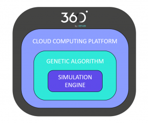
The incredibly flexible architecture of 360™ allows for covering analysis needs from feasibility up to detailed design and operations planning. Specifically, 360™ includes more than 15 modules that are critical for the analysis of space mobility. A list of these includes:
- Electric and chemical propulsive maneuvers design and optimization (station-keeping, de-orbiting, orbit transfer, etc.)
- Propulsion systems comparisons and trade-off analysis
- Design and optimization of spacecraft subsystems (propulsion, power subsystem, attitude, etc.)
- Concurrent optimization of maneuvers and subsystems
- Optimization and planning of propulsive phases and operations (space mobility digital twin)
- Satellite constellation mobility (deployment, maintenance, and refurbishing) analysis and optimization
- And many more!
Why is having a tool like 360™ so important? Having a modular propulsion system brings additional complexity to the mission design. In effect, to be fair, the selection of a propulsion system (even a COTS one) is not a simple feat as we have seen through the case study. Since, while being dependent on the ΔV-budget and thrust requirements from the mission analysis, it is also strongly coupled to the attitude dynamics, and the behavior of other subsystems, and it is subject to intricate operational constraints and complex inter-coupling with many other disciplines. To make some examples:
- The attitude control system must be able to handle the torques generated by the thruster, and if no gimbal or other control system is embedded in the propulsion system, it must track the required attitude to perform the maneuvers.
- The Electrical Power System (EPS) must be able to sustain high-power consumption for long durations, also considering eclipse periods where the batteries must be able to sustain the spacecraft. The thrusters can be turned off strategically, but clearly, the knowledge of the evolution of power onboard is critical.
- From the thermal point of view, some propulsion systems require very careful considerations: for example, chemical systems and some electric ones as well (like Hall thrusters) can run quite hot, and much care must be put into this.
Thus, having seen the number of interdependencies and the complexity that exists in selecting the adequate propulsion system, it becomes clear that IENAI’s cutting-edge software tool for space mobility analysis: 360™, allows having a holistic view of the problem.
→Check out the full paper!
→Register for GO™ and create your custom thrusters!
![]()